Electroacoustic systems
Public address systems (PA systems)
Public address systems are usually mono. They typically distribute one or more audio signals into different areas that we call zones. The type of audio signal can either be background music, manual or automatic announcements, or signal tones (gongs, alarm tones). The audio signals are normally not mixed. An audio signal is transmitted into one or more defined zones.
Priorities are assigned to avoid the inadvertent merging of different audio signals, e.g. if multiple announcements are to be broadcast in the same zone at the same time. Most PA systems work using high-impedance loudspeakers.
Central PA system
For a central PA system, the speakers are all installed in the same location, e.g. in the middle of a hall‘s ceiling.
Frontal PA system
If the sound is accompanying an optical event, the sound should also be originating from the direction of this event. The viewer becomes irritated if the sound comes from another direction. In most cases, such an event takes place at the front of the room, for instance on the stage. The loudspeakers are usually positioned to the left and right of the event. The loudspeakers should also be mounted high enough that the sound pressure is not too high in the vicinity of the listeners, not least to prevent the audience’s hearing from being damaged.
If the room in question is deep, loudspeakers can be installed along the wall or ceiling (‘delay line’) to support the front PA system. In order to ensure that the frontal signal remains intelligible, these speakers should reproduce sound with a delay (adjusted individually, depending on the distance from the frontal system). This gives the impression that the sound is coming directly from the stage. The delay can be calculated using the following formula: T = d / 340 + 0.01 s
T: Time of delay (s)
d: Difference in distance from the listener front loudspeakers/delay loudspeakers (m)
Decentralized PA system
If no support is required for directional staging, or in large spaces with low ceilings (e.g. supermarkets), installing a frontal PA system is not useful. In such cases, it is better to go with a decentralised PA system in which the loudspeakers are installed where they are needed.
The ceiling loudspeakers should be distributed evenly over the PA system’s effective area, generally with the same spacing between all the loudspeakers. The required degree of intelligibility is an important parameter in planning such a PA system. This depends on several factors:
- Ceiling height
- Loudspeaker coverage angle
- Type of use (quality of sound)
The higher it is possible to mount the loudspeakers, the greater the effective range of the loudspeaker and therefore also the acoustic range at ear height (ear height ≈ 1.5 m above the floor), yet the sound pressure is lower than would be the case for a lower installation.
For good intelligibility, the frequency response of the system should be able to reproduce signals of up to 6 kHz at every point in the audience area. Acceptable intelligibility is assured at a frequency response of up to 4 kHz. This value should be ignored in the case of background music, since background music is not a matter of intelligibility
Amplifier
There are PA system amplifiers for low-impedance loudspeakers with impedances of between 4 and 16 ohms, for high-impedance loudspeakers (frequently 50 V, 70 V and 100 V), and some for both types. For low-impedance loudspeakers, only short cables (up to 10 m) should be used, or cables with large core cross-sections, in order to keep cable losses low and to ensure good audio quality. Only a few loudspeakers can be operated from a low-impedance amplifier. High-impedance loudspeaker systems allow long cable lengths and multiple loudspeakers on one line.
Low-impedance technology
For low-impedance systems, it is important to remember that the total impedance of the connected loudspeakers may not be less than the minimum terminating impedance of amplifier. If the total connected loudspeaker impedance is too low, this will cause malfunctions and may damage the amplifier. The cables between the amplifier and loudspeaker(s) should not be longer than around 10 m. If the cables are longer than this, line losses will be too great, which in turn should be reduced by employing large cable cross-sections in order to obtain good audio quality.
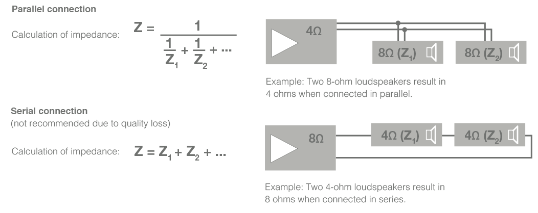
At a serial connection only identical loudspeakers should be operated from a single amplifier, as the power distribution for different loudspeakers depends on the circuit and impedance.
High impedance technology
In a PA system designed for large areas, high impedance technology is preferable in order to minimize line losses. High-impedance systems are characterized by a maximum signal line level of up to 100 V at full signal conduction. High-impedance transmission paths are also realised using 70 V or 50 V in order to provide better compatibility in terms of level adjustment and subsequent system expansions. High impedance technology offers other benefits over low-impedance systems as well:
-
Easy installation, easy to expand & increase the number of loudspeakers (parallel connection)
-
Possible to incorporate large number of loudspeakers
-
Individual volume control possible for each loudspeaker, individual loudspeakers can be switched on and off without affecting other loudspeakers
-
Different loudspeakers with different power ratings can be operated together in a single loudspeaker line
-
Long cable lengths / long distances possible
-
Low cable diameter of loudspeaker wire
-
Low line losses
-
Simple to calculate the required amplifier power by summing the powers of the individual loudspeakers, which must not exceed the rated power of the amplifier

Check loudspeaker lines
To avoid electrical problems after modifying existing PA systems or installing new ones, the loudspeaker lines should be checked before connecting to the amplifiers. This is done by performing a line impedance measurement.
The following formula shows the relationship between electric power, maximum signal amplitude and impedance:
Z = U2 / P
Z: Impedance (ohms) U: Voltage (volts) P: Power (watts)
The calculation has to be performed taking into account a maximum signal amplitude of 100 V (10,000). Example: Loudspeakers with a total power of 75 W were interconnected on a single loudspeaker line. What is the impedance of the loudspeaker line? Z = 10,000 / 75 = 133 ohms
Dependency between loudspeaker wire’s crosssection area and cable length
The table below shows the dependency of the necessary wire cross-section area on the length of the cable. In PA systems, the loudspeaker line is designed in such a way as to limit the losses to a maximum of 10%.
Wire cross-section area in mm²
| Cable length | |||||||||||
| Power | 50 m | 100 m | 200 m | 300 m | 500 m | 750 m | 1000 m | |||||
| 30 W | 0,05 | 0,09 | 0,19 | 0,28 | 0,47 | 0,71 | 0,95 | |||||
| 60 W | 0,09 | 0,19 | 0,38 | 0,57 | 0,95 | 1,42 | 1,89 | |||||
| 120 W | 0,19 | 0,38 | 0,76 | 1,13 | 1,89 | 2,84 | 3,78 | |||||
| 240 W | 0,38 | 0,76 | 1,51 | 2,27 | 3,78 | 5,67 | 7,56 | |||||
| 360 W | 0,57 | 1,13 | 2,27 | 3,40 | 5,67 | 8,51 | 11,34 | |||||
| 420 W | 0,66 | 1,32 | 2,65 | 3,97 | 6,62 | 9,92 | 13,23 | |||||